Durafly Auto G/G2 Tractor to Pusher
Conversion Kits
Note: Originally we were planning on
selling the MIA EZ 1.5 Gyro
as the Auto G/G2 conversion Kit, but
it proved to be too large
for the Auto G/G2 Blades so we went
with the 1.25 Instead.
Before
You Start Please familiarize yourself with the Kit and
Instructions Pay particular attention to the two Carbon
Rod diameters used
for the
Vertical Stabilizer Support (M2) and Vertical
Stabilizer to Rudder Hinge Pin (M1.5)
The kit assembles fast since it is 99 % bolt-on. Stain
or Clear Coat the Oak wood frame or paint as desired
before assembly. Let the parts dry completely before
bolting on the frame brackets and supports.
The only parts that need permanent CA gluing are the
Vertical stabilizer carbon rod supports, these must sit
totally perpendicular with the base and in line with the
main mast. Also the Motor Mount, as per instructions
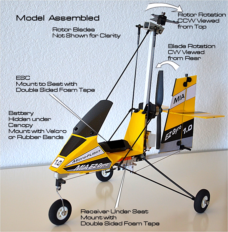
The Electronics in the kit contains a JST Power
connector, make sure to test the rotation of the motor
CW as seen from the rear
before soldering the motor to esc wires. Check and
double check polarity of Battery connectors before
soldering or making connections.
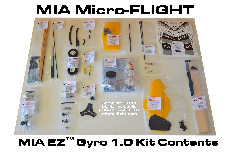
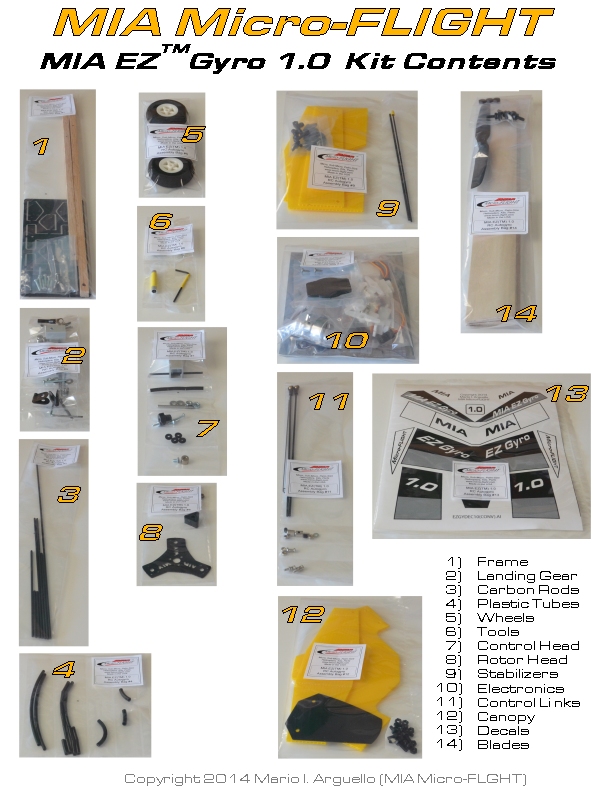
Kit Contents
Materials and Tools Required
* Hot Melt or High quality CA Glue, CA
Accelerator Spray
* A 00 size Philips Screwdriver
* Exacto™ Hobby knife
* Small Scissors
* Metal Edge Ruler
* Krylon™ Paint for Plastics (Optional to paint frame to desired
color)
Note: Frame Mast and Base are made from high quality oak wood.
If you favor a natural oak look, like in our main product photo,
suggest you stain the wood lightly and coat with a couple light
coats of clear coat. If you favor a Sporty look, coat with color
of choice, use Krylon paints for wood/plastics, suggest you
select a color that blends with Industrial Yellow, such as Black
or White (like in our Instructions Photos) and can be easily
seen up against a blue sky.
Required Equipment
PLEASE DO NOT DEVIATE FROM THIS EQUIPMENT ESPECIALLY THE
REQUIRED USER SUPPLIED FLIGHT BATTERY SIZE AND CAPACITY. PLEASE
ASK MIA, IF IN DOUBT
* Transmitter -- Programmable Delta Elevon Mix, DX6i DSM, Hobby
King Orange TX Mode2 or similar
* Receiver -- Spektrum DSM, or Hobby King Orange RX DSM2 6CH
* Battery -- 500mAh 20 to 30C 2S 7.4V (Beginner)
3S 11.1 volts ( Expert)
* Suitable Li-Pol Charger
Note: Please observe Li-Pol Battery and Charger Manufacturer
suggested instructions for operation. You are solely responsible
and assume all liability for operation of model.
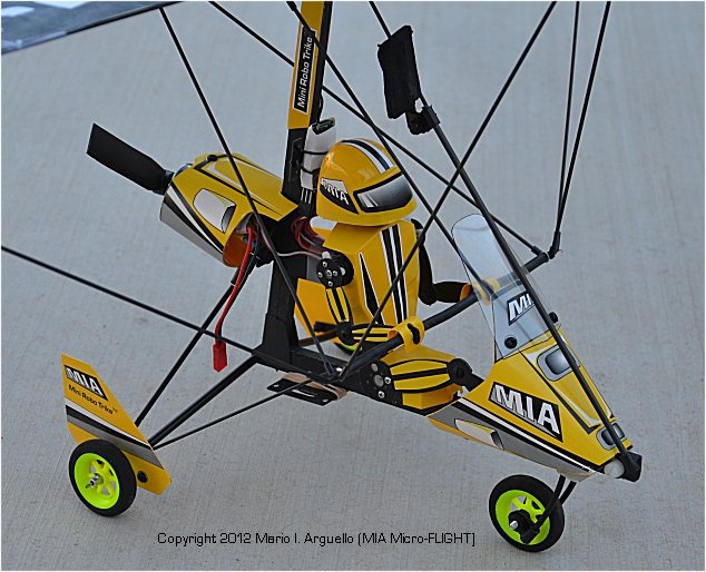
2014 Bolt-On Frame Version
Please use the photos as general
reference through the model assembly
If you have any questions please
don't hesitate to E-Mail me
I'll be happy to assist you during
the build, setup and flying. Mario
! Vertical and Horizontal Motor Offset
Correction !
(See Motor Installation Steps)
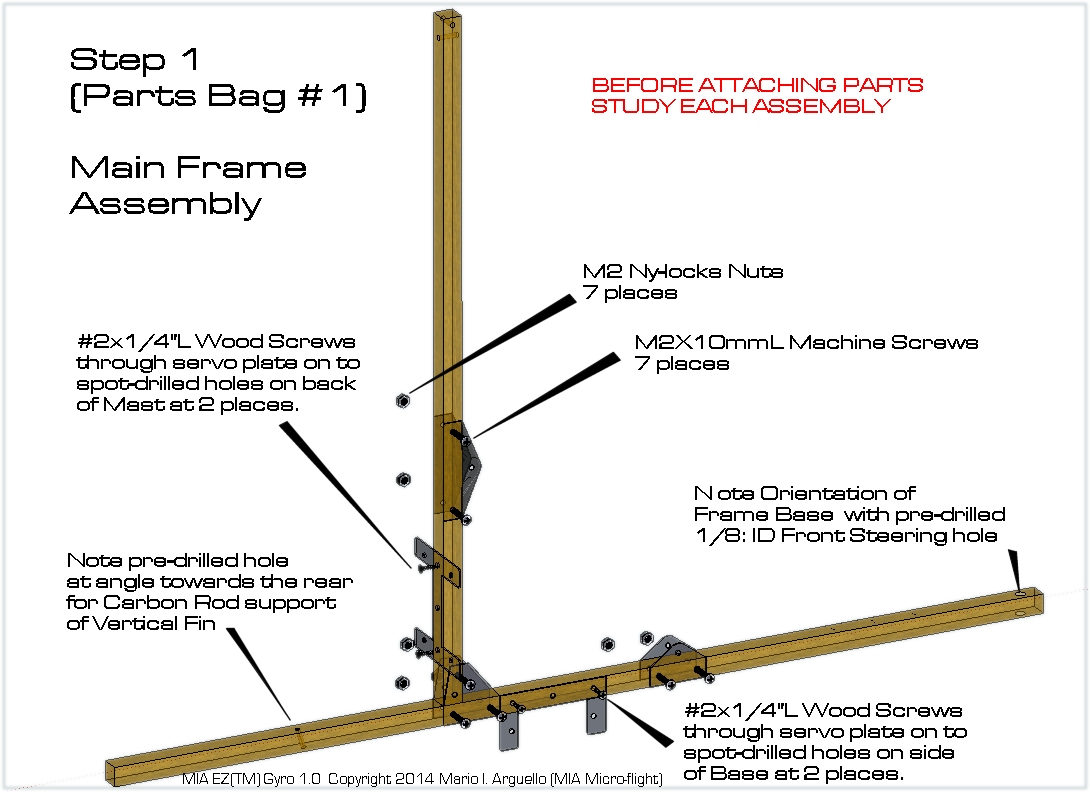
Please Follow these Build Steps in the Sequence Indicated
Mast and Base should be at 90
Degrees
before tightening all bracket bolts
and nuts
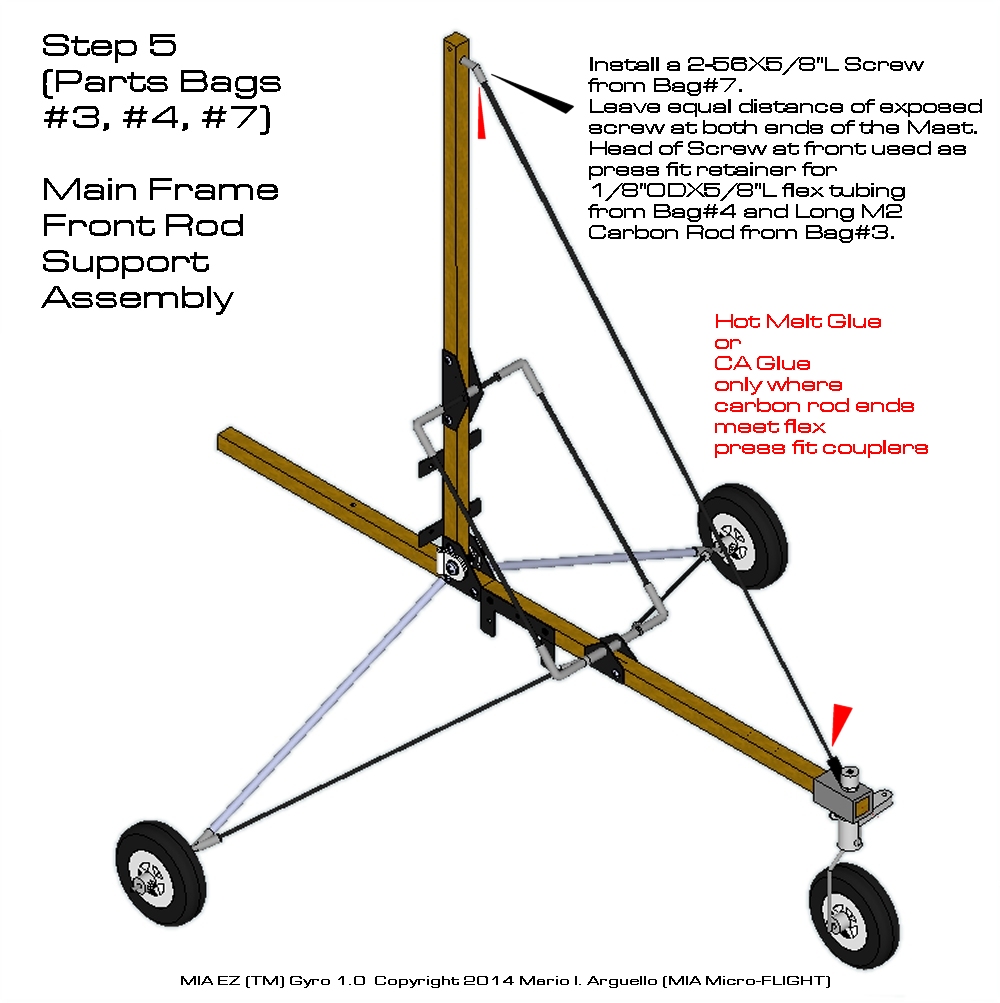
The Flex tubing, carbon rods and
hardware for larger MIA EZ Gyros will be larger
but same assembly applies.
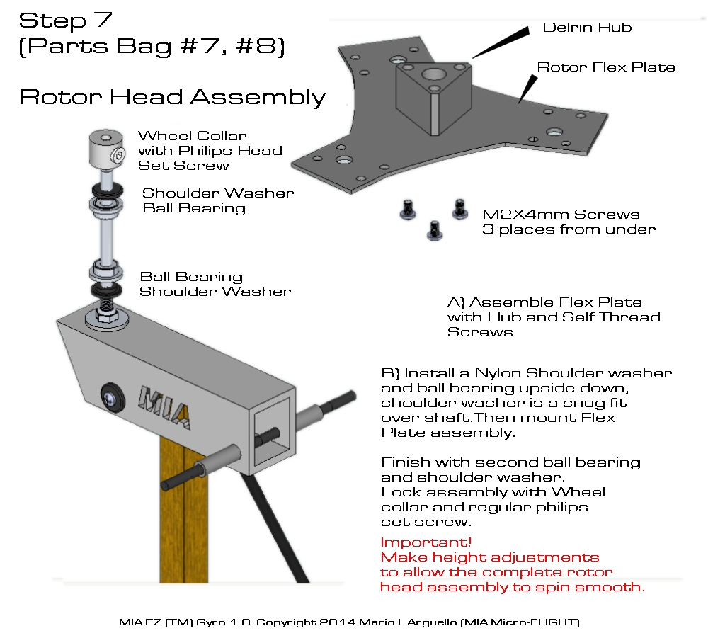
The Rotor Shaft on the larger MIA EZ
Gyros is a Machined Long Bolt
but attaches In the same way t o the
Control Head.
The Hub on the larger MIA EZ Gyros
has been simplified
and it may come installed already
with ball bearings. The Retainer for these is via a locknut
(instead of a wheel collar) with a machined step that goes
towards the top ball bearing. Simply install rotor assembly over
the screw shaft machined to fit the ball bearings (No
spacers required on the 1.25 gyros) the shaft screw will
have a natural stop that holds the rotor assembly from
bottoming down. DO Not over tighten the locknut.
USE OF LOCTITE or GLUE on
UNIVERSAL JOINT PARTS
ONLY AND ONLY FOR UNIVERSAL JOINTS THAT
USE METAL COMPONENTS,
AS ON SOME OF MIA MUCH LARGER EZ GYROS.
DO NOT USE WITH NYLON OR PLASTIC
UNIVERSAL JOINT PARTS AS THESE BEING MADE FROM STRONG DELRIN-NYLON
AND MACHINED FOR SELF THREADING SCREWS HAVE NATURAL RETAINING
PROPERTIES AND DO NOT REQUIRE LOCTITE.
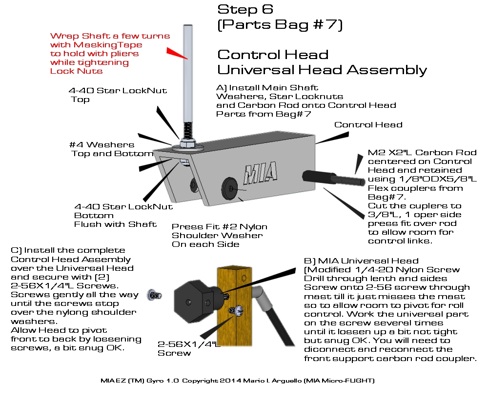
CONTROL LINKS
The Control Links simply install over
the ends of the Control Head Carbon Rod
and are retained with press fit flex
or spline rubber tubing. For a more secure and permanent
installation place a small drop of CA Glue at the end of the
carbon rod where it meets the end of the press fit ball link
retainer tubing.
On he larger MIA EZ Gyro kits, the
ball links need to be installed to the carbon rods
supplied with them. Place a
small drop of CA Glue inside the Ball link stem
and insert the carbon rod all the
way. Let this dry completely before use.
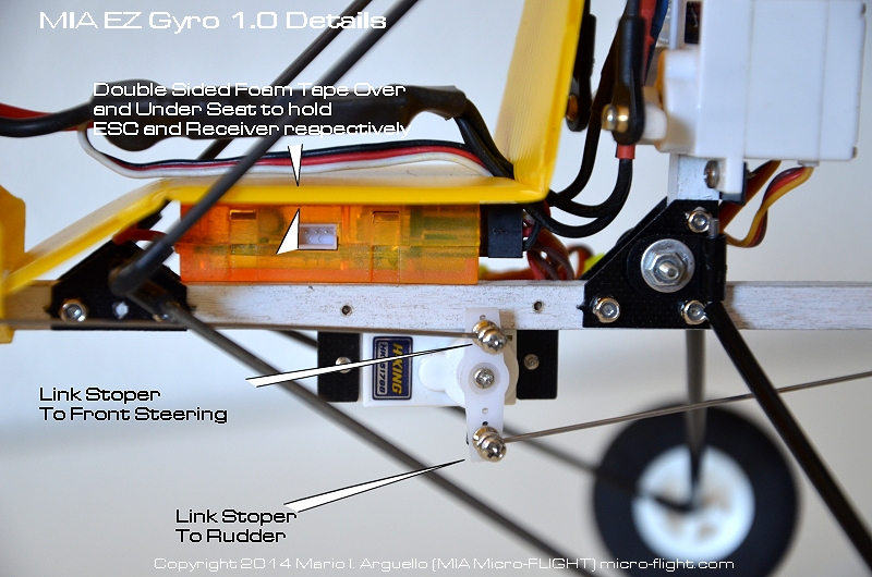
The bottom of the assembled links go
into a link stopper to the servo horns. Note there are two sizes
of link stoppers and these are drilled to accept the correct,
either Carbon or wire link. The carbon rod control links are
larger diameter than the wire "Z-Bent" control links for the
steering and rudder.
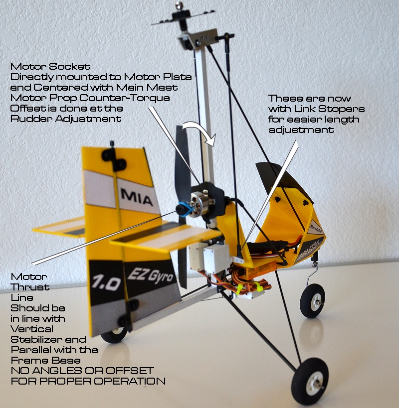
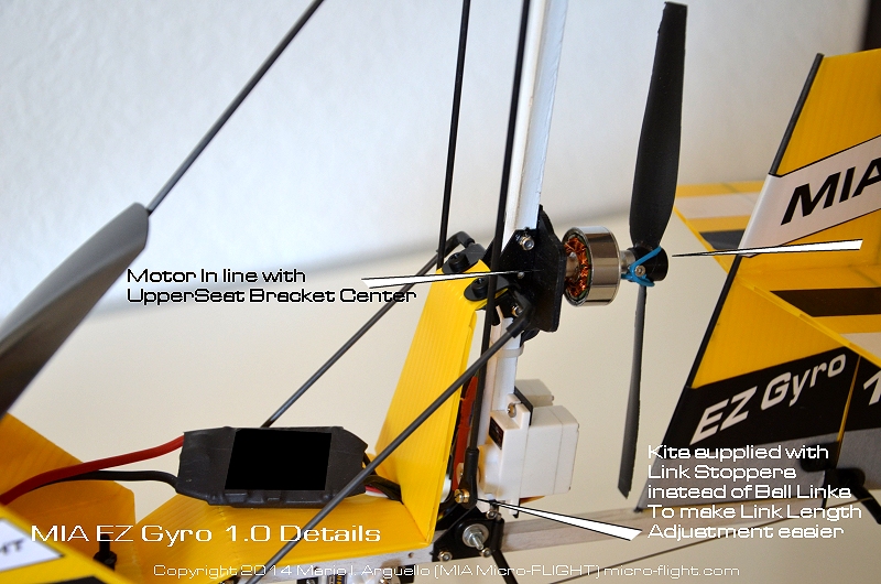
MOTOR INSTALLATION
The motor support part of the electronics bag, must be mounted
center with the Rear Seat Upper bracket so that the 6x3 propeller
clears the base by approx 1/8 inch. Do not install the motor any
higher than this reference as these calculations are important for
the efficient operation of the model.
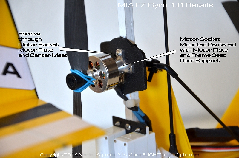
Once this is established you may want to secure the motor mount,
the black painted wood part) more securely to the mast with a bit of
CA around the area where it makes contact with the mast.
The mounting screws supplied with the motor mount should go through
the metal motor mounting socket, the wooden support plate and 1/2
way through the mast. Make sure this install is aligned and the
motor thrust line is in line with the Vertical stabilizer also in
line with the base.
Motor Vertical Offset
It is extremely important that the motor
have a vertical
offset with the tail horizontal
stabilizer of about 2-3 degrees UP.
The way to accomplish this is by shimming
the motor mount, the lower portion, about 1/32" this will allow
the model to take off straight and with the nose up. Otherwise
the model will have a tendency to sink.
Make sure the Motor Offset is with the frame mast at 90 degrees
with the base, any deviation here will throw off the vertical motor
offset. Model straight and level take-offs also depends on the
Rotor Head Assembly angle of attack, this is normally at 98-100
degrees with the Control Head pointing upward and in reference to
the mast.
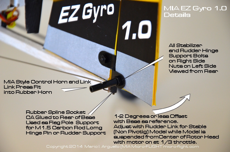
Motor Horizontal Offset
There is no horizontal offset on the actual
motor install, because the rudder does this to keep the model in
balance by slightly pre-trimming its angle to counter-act the prop
torque. This is done while the model is suspended from the center of
the rotor shaft with a heavy string and the motor carefully
throttled up.
Make Slight rudder adjustments with the rudder
servo at trim position and using the rudder servo link-stopper to
make the adjustment. These adjustments are made with motor and prop
at 1/3 power until the model sits still (does not pivot or
pivots at minimum while suspended as described). A bit of trial and
error is required to get the model trimmed for horizontal offset
balance.
You could horizontally offset the motor as
some DIY enthusiasts do it on their rc autogyros, but the
motor must be installed in line centered with the mast so that the
mounting screws of the motor also grab on to the mast center
for more support. Finally, CA Glue the motor plate only (not the
aluminum motor socket) to the mast for a more permanent
installation.
This method also keeps lateral balance in
check. Real Autogyros typically offset the Vertical stabilizer or
the rudder. The Rudder is much easier to offset in an RC model since
it is angle adjustable via the steering-rudder servo link and link
stopper or link length adjust mechanism.
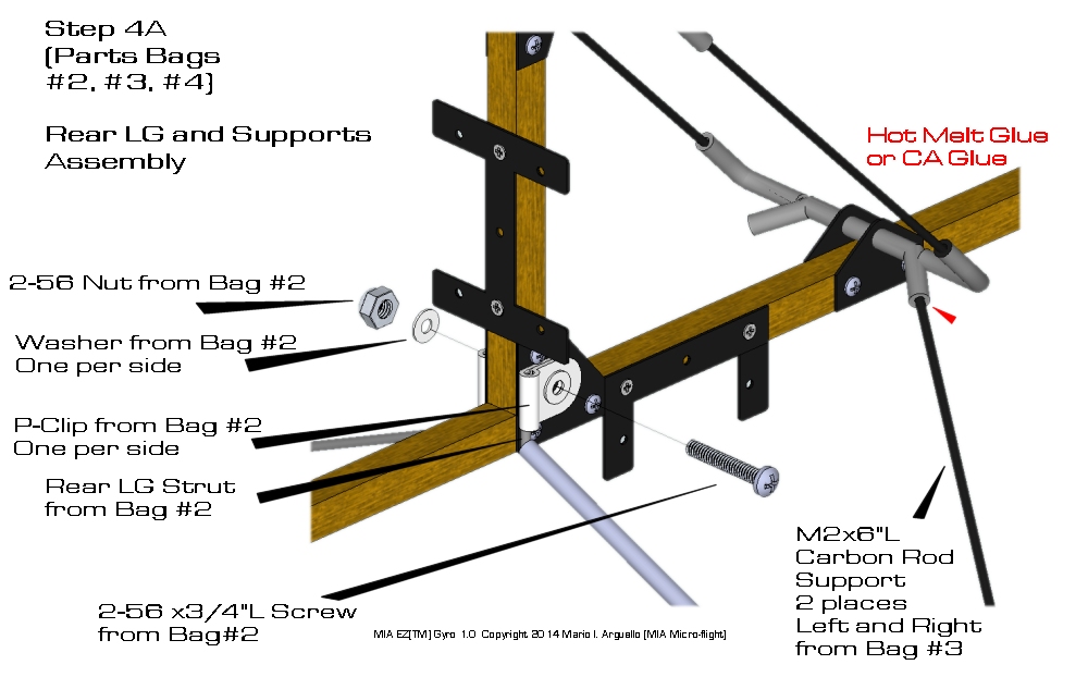
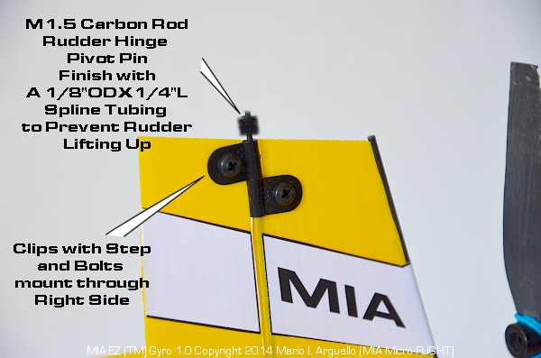
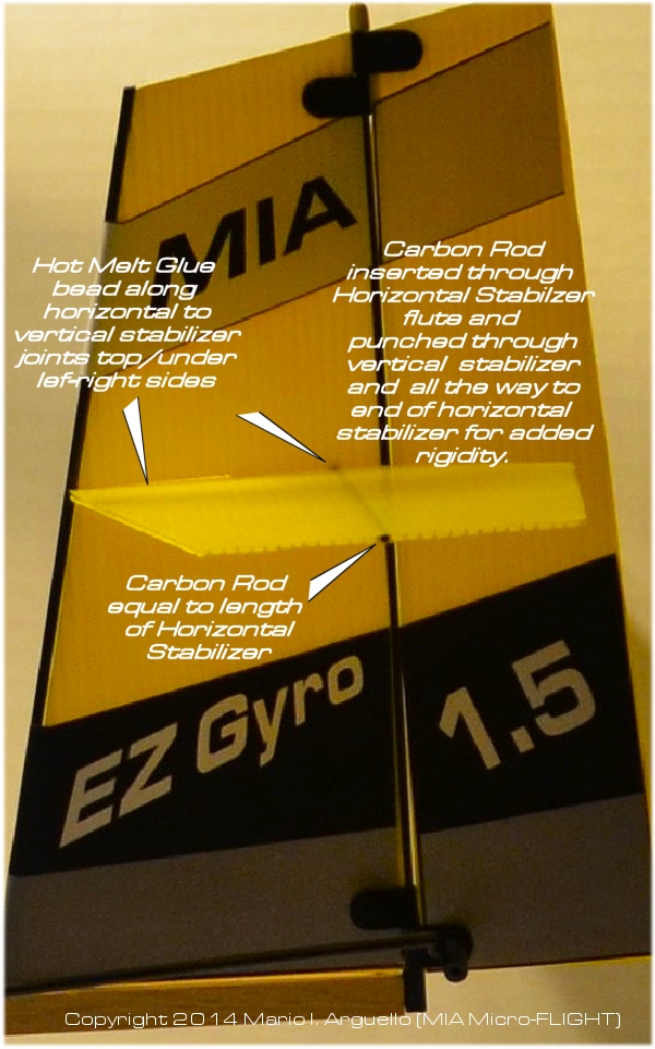
INSTALLATION OF STABILIZERS
The Vertical
Stabilizer front end is supported by a M2 Carbon rod which
gets located on the rear of the mast at a preset drilled
angled hole, while the rear of the Vertical Stabilizer and
also Pivot Line for the Rudder locates on an M1.5 Carbon
rod to allow the hinged plastic parts to pivot along with
the rudder. This later rod also gets located at the bottom
inside a rubber piece of spline tubing CA Glued at the
rear of the frame base, like a flag pole support.
The top of the M1.5
hinged carbon rod gets also a piece of rubber spline tubing to
lock the rudder from lifting up from the hinges.
Super easy once you
study the photos and Installation Illustrations.
For the
larger MIA EZ Gyros the carbon rods will be larger but the
same OD on both the front support and rudder hinge
Decals for
the Vertical Stabilizer Front are simply trimmed and
wrapped around the Carbon Rod support and Stabilizer
Edge to secure in place.
Apply the
decals before any hardware is installed, you may need
to punch holes
through the decal where a clip goes, use the clip hole as your
template.
IMPORTANT ANGLES
Rotor Control Head Angle
of Attack:
98-100
Deg. with mast as reference
Rotor Control Head Angle Lateral:
0 Deg. Straight
Horizontal
Vertical Motor Offset:
2-3 Degrees up towards the
back
Horizontal Motor Offset:
With model suspended via string attached to rotor
head shaft, basically the rotor center "Hang Point",
adjust rudder angle via the rudder control link for minimum to
zero
model rotation about the rotor head hang point.
Hang
Angle:
8-12 degree Rotor "Shaft" Inclination towards the
nose from vertical.
Done with 3 cell
500 mah Li-Pol installed all the way inside the cabin
front end and with model suspended via string
attached to rotor head shaft (basically the rotor
center).
Rotor Control Head
Throw Lateral
(Left Aileron
or Roll)
12
Degrees
Rotor Control Head Throw
Lateral (Right Aileron or Roll)
12
Degrees
Rotor Control Head
Throw Vertical (Elevator or Pitch)
6
Degrees
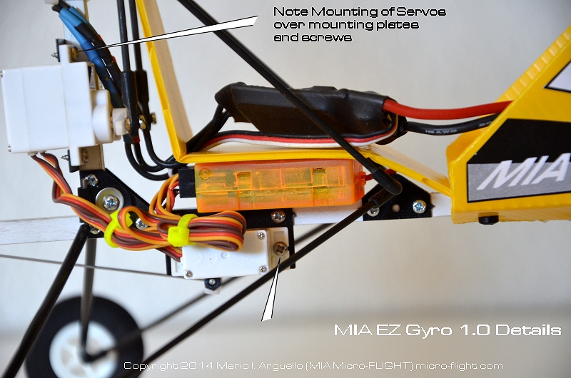
RC EQUIPMENT INSTALLATION
Keep in mind the installation of the RC
equipment.
It is important to keep the receiver, esc and battery in the
suggested locations for proper weight balance distribution.
The battery is installed all the way in front of the nose of the
Cabin with rubber bands around the base and over the battery, Velcro
or double side tape to the cabin inside walls and centered with the
base.
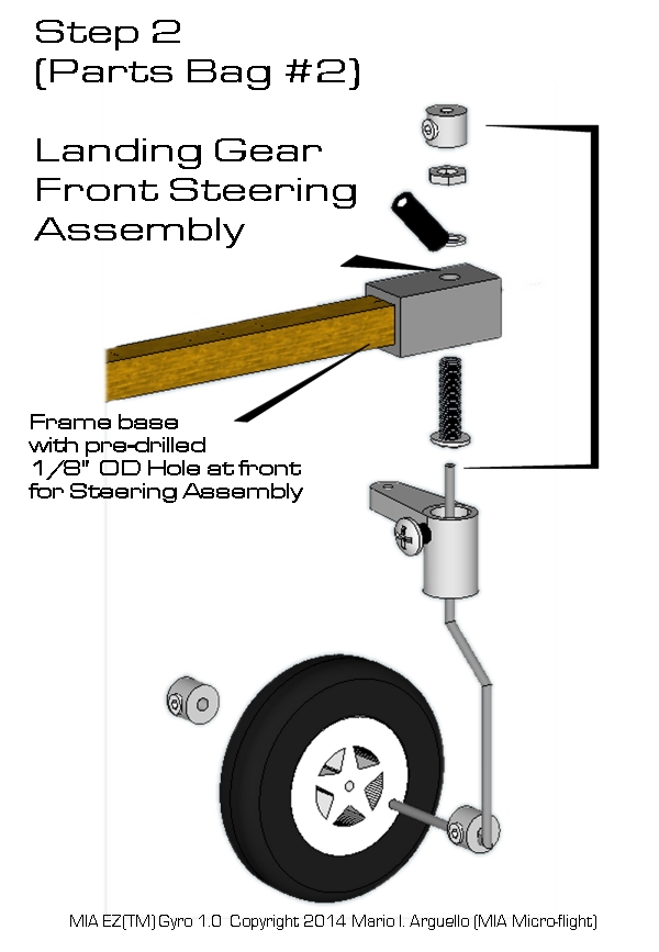
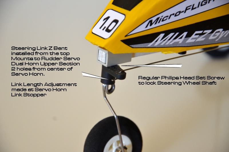
STEERING AND RUDDER
In order to install the link stoppers, you
need to "SLIGHTLY" enlarge the servo horns holes so that the
stoppers mounting pegs fit a bit snug but are able to pivot.
Front Steering Servo Horn Upper 2nd hole
Rudder Servo Horn Lower 3d Hole
The Z-bent wires are supplied extra long.
Once installed, trim them with an abrasive cut-off wheel,
Dremel tool, or wire snipers, leaving 1/4" extra, sand or grind
the trimmed ends of the wire smooth.
ROTOR BLADES INSTALLATION
With the MIA EZ Gyro conversion kits for the
HK Durafly Auto G/G2 where you are reusing the Auto G blades, the
same balancing check applies.
The blades are unique as they have MIA's
own profile and way of manufacturing. They have been weighted and
balanced but as with any rotating prop or blades, check the
balance again. This is done with the blades installed on the rotor
head and spread out evenly at 120 degrees, on the rotor flex
plate, via the single pivot mounting bolt installed snug but not
overly tight.
Give them a manual spin and check for
vibrations. The rotor with blades should spin smooth when blades
are properly positioned on the rotor head. If there are slight
unbalances, make slight blade position adjustments, in many cases
this is all that is required, but if this is not the case, adjust
the balance. If required, you can do this also by holding
the model on the side and let the rotor sit vertically and find
its own gravity center balance. Then see which blade is lighter,
and add small pieces of masking tape to the lighter blade to match
the rest equally. Do this patiently until the whole rotor
spins even and smooth.
The blades are one piece. During heavy
testing they have proven highly durable and able to withstand a
lot more abuse than typical wood-balsa rotor blades or even foam
molded ones like on the Auto G.
The rotor head is the same as the MIA Upgrades head we make for
the Auto G but relatively smaller and it does not use the shim
screws on the rotor flex plate, instead the blades have their own
shim part, on the blade. Please do not be tempted to put
additional shims on the rotor flex plate, or blades, as this will
bog down the operation of the model.
FLYING TIPS
With the model setup properly, the rotor
blades typically spin up quickly by a moderate breeze or by hand
and no pre-rotator is required, but note that before lift-off,
they should be in full RPM (by the swoosh sound and by the model
wanting to lift off from your hand, if you hand toss it).
This is critical in autogyros and you
must remember to keep the rotor spinning at all times by managing
throttle control.
This takes a bit of practice if you are
not familiar with RC autogyros. Please watch the MIA EZ GYRO
Videos and study the way I fly them, you can learn a lot by
doing this if you do not have an RC autogyro pilot assistant next
to you.
Also, it it is better to start with
a 2-cell 500 mah Li-Pol battery until you get the hang of it,
while gently tossing the model straight and level, once you get
the rotor to spin up to full speed. Then go to 3-cell 500 mah Li-Pol
battery. A 3-Cell battery will give you a lot of power! so go easy
on the throttle (typically 1/3 should get the model airborne with
hand tosses).
Ground Take-offs take a bit of practice
and patience is the key here. With the model pointed towards the
breeze or mild wind, gradually throttle up to get the model moving
and the blades picking up speed. Make sure you have all the
Critical angles dialed in, this will get the model in the air
straight and easier.
Adjust the nose steering if too sensitive
by the rudder servo horn link hole, closer to the center of the
horn or via the mechanical steering link adjuster (not by the
transmitter setting). The rudder Sensitivity is also important,
try not to use ruder control during take-offs and start with LOW
RATES as described in the Transmitter Settings.
If you think your model is going to crash
or is in trouble, simply lower the throttle and allow the model to
parachute down. Typically, autogyros do not stall and will simply
parachute on their own weight and rotor rpm.
The MIA EZ Gyro Blades have built
in self stabilizing momentum by nature of design and material
density and will keep spinning after the throttle is removed, but
keep in mind that rotating devices also come to a stop at some
point even if they are mounted on ball bearings.
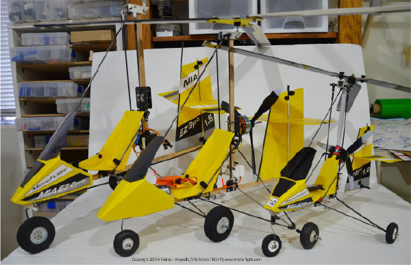
Larger version of the MIA EZ Gyro 1.0
Shown here for Flight Training Purposes
TRANSMITTER SETTINGS
MIA GYRO (WING TAIL MIX FOR STANDARD
ELEVON SETUP)
(DX6I TX or HK T-SIX Transmitter with respective matching
Receivers)
RIGHT SERVO
( RECEIVER ELEV CH. )
LEFT SERVO
(RECEIVER AILE CH.)
As seen from the back of the model
the Rotor should tilt to the right upon Right Aileron
stick control, and tilt back upon UP Elevator stick
control (when you pull the ELE stick towards you)
Recheck the Servo Reverse settings with your particular
Receiver connections.
Servos are connected to the Orange
HK receivers in the same order as described in this table.
Aile to Aileron, Ele to Elevator, Rud to Rudder.
EXPERT DUAL MIX SETTINGS are in RED
Use this with the Transmitter MIX
switch on the DX6I to toggle from Normal to Ultra High
AILE and ELEV Throws and vise versa. Useful for easier
ground take offs, by pitching the rotor further back to
allow the rotor to spin faster when faced against the
wind. As soon as model lifts off, toggle the MIX switch
back to Normal, otherwise the control will be very
sensitive! Do Not use this for hand toss take offs.
The start of the video MIA EZ GYRO
1.0 Part B illustrates the use of the dual MIX Setting via
the MIX Switch.
FUNCTION LIST
MODEL SELECT
MODEL 1
D/R
AILE 0 75%
EXPO
+ 75
AILE 1 50%
+75
ELEV 0 75%
EXPO
+ 75
ELEV 1 50%
+75
RUDD 0 50%
EXPO
+ 75
RUDD 1 25%
+75
TRAVEL ADJ
THRO 100%
AILE 125%
ELEV 125%
RUDD 100%
GEAR 100% (not used)
FLAP 100% (not used)
SUB TRIM
THRO 0
AILE 0
ELEV 0
RUDD 0
GEAR 0
FLAP 0
FLAPS
NORM
FLAP 0
ELE 0
LAND
FLAP 0
ELE 0
MIX 1
AIL-AIL
INHIBIT
MIX1 (EXPERT)
AIL-AIL
ACT
RATE
L +125%
R +125%
SW
MIX
TRIM
INH
MIX 2
ELEV-ELEV
INHIBIT
MIX 2 (EXPERT)
ELEV-ELEV
ACT
RATE
U +125%
D +125%
SW
MIX
TRIM
INH
DIFFERENTIAL
INHIBIT
SETUP LIST
MODEL TYPE
ACRO
MODEL NAME
MEZGYRO1
REVERSE
THRO
N
AILE
R
ELEV
N
RUDD
R
GEAR (not
used)
N
FLAP (not
used)
N
THROTTLE
CUT
POSITION
INH
WING TAIL MIX
DUALAILE
INH
V-TAIL
INH
ELEVON
ACT
D/R COMBI
D/R SW
INH
TIMER
MDL1
MEZGYRO1
DOWN
TIMER
10:00
SWITCH
TRAINER
RANGE CHECK
CHECK
INH
POWER SETTING
B-US 247
MODULATION
TYPE
AUTO DSM-X
ENABLE
DSM-X AND
DSM-2
STANDARD
RECEIVERS
TX SETTING
BATTERY TYPE
Normal
4S
4.3V Min
NIMH
4S
4.6V Min
LI-POL
SOUND MODE
On
CONTRAST
(if you have
back lit LED transmitter screen)
50%
BACK LIGHT
COPY /RESET
STK MODE
MODE 2
THRO-RUDD
ELE-AILE
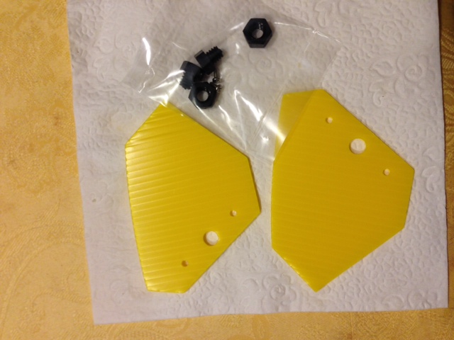
Wheel Fin Parts (Optional Accessory)
Theory Behind LG Rear Wheels Fins
Besides adding a finishing touch to the trike LG, weather in "microlights"
or "autogyros", is that they are designed to enhance
directional "yaw" stability. These are more effective on "microlights"
since these typically have no rudder.
You can fly the model without them
just fine, all the MIA EZ Gyro 1.0 early videos are done
without them, but if you decide to install these parts,
you may notice a bit more yaw stability in trade off for a
slightly tail heavier model.
MIA EZ Gyro 1.0 Optional Wheel Fin Assembly is as follows:
1)
Take one of the modified screws and and nut and compress
them " finger tight" around the fin. Don't use glue!.
Disregard the 2 small fin holes and only use the large
center one. The installation as described is
forgiving in a crash as the fins will simply pivot on the
mounting (compression screw-nut) thus the logic behind
"finger tightened".
2)
The small screws part of this accessory kit, are set
screws, the nuts have been drilled to accept these screws
" self threading"
like regular wheel collars
(Do not over tighten these as they can strip the plastic).
Install in lieu of the outer LG rear wheel metal collars
with the fins vertically.
The same fin shape is used on the MIA Mini Robo RC
Microlights but they
mounted on the inside of the wheels, via a different
mounting hardware and method.
SUPPLEMENTAL PHOTOS and VIDEOS
If you have any question
please E-mail me directly for assistance.
Note that the MIA videos posted here
on this page have also information for successful
flights. Go over them carefully.
IMPORTANT! DO's and DON'Ts
Before you FLY for the first time, and to ensure a higher
level of success and enjoyment, please do a ground check
of your model build, and setup or allow me to do it for
you via Email. Email me high resolution photos or a video
of your build as seen from the side front and back and I
will give it a final check for you.
DO NOT modify the design of any of the parts
Install a bigger propeller than original GWS 6X3 Prop
Install a bigger Battery than recommended Li-Pol 3S 500
mah Max.
Leave model in the heat, enclosed car, hot or damp area.
Please follow RC equipment
manufacturer recommendations, in particular with Li-Pol
batteries and chargers.
When Testing or Flying, keep model away from people,
animals, high tension lines and obstacles. Please use
caution and common sense when operating an RC model with a
rotating propeller or rotor.
You are fully responsible
for the operation of this model.